By SGI Fellow Xinwen Ding and Ahmed Elhag
During the third and fourth week of SGI, Xinwen Ding, Ahmed A. A. Elhag and Miles Silberling-Cook (week 3 only) worked under the guidance of Benjamin Jones and Prof. Adriana Schulz to explore methods that can define a continuous relaxation of CAD geometry.
Background
In general, there are two ways to represent shapes: explicit representations and implicit representations. Explicit representations are easier to model and allow local differentiable parameterizations. CAD geometry, stored in an explicit form called parametric boundary representations (B-reps), is one example, while triangle mesh is another typical example.
However, just as each triangle facet in a triangle mesh has its independent parameterization, it is hard to represent a surface using one single function under an explicit representation. We call this property discrete at the global scale. This discreteness forces us to catch continuous changes using discontinuous shape parameterization and results in weirdness and artifacts. For example, explicit representations can be incompatible with some gradient-based methods and some neural network techniques on a non-local scale.
One possible fix to this issue is to use implicit shape representations, such as signed distance field (SDF). SDFs are global functions that are continuously differentiable almost everywhere in the domain, which addresses the issues caused by explicit representations. Motivated by this, we want to play the same trick by defining a continuous relaxation of CAD geometry.
Problem Description
To define this continuous relaxation of CAD geometry, we need to find a continuous relaxation of the boundary element type. Consider a simple case where the CAD data define a geometry that only contains two types; lines and circles. While it is natural that we map lines to 0 and circles to 1, there is no type defined in the CAD geometry as the pre-image of (0,1). So, we want to define these intermediate states between lines and circles.
The task contains two parts. First, we need to learn the SDF and thus obtain the implicit shape representation of the CAD geometry. As an alignment to the input data type, we want to convert the type-blended geometry to CAD data. So next, we want to convert the SDF back to valid boundary representation by recovering the parameters of the elements we encoded in the SDF and then blending their element type.
The Method
To make it easier for the reconstruction task, we decided to learn multiple SDFs, one for each type of geometry. According to these learned SDFs, we can step into the process of recovering the geometries based on their types. Now, let us consider a concrete example. If we have a CAD shape that consists of two types of geometries, say lines and circles, we need to learn two SDFs: one for edges (part of circles) and another for arcs (part of circles). With these learned SDFs, We hope to recover all the lines that appear in the input shape from the line SDF, and a similar expectation applies to the circle SDF.
Before jumping into detailed implementations, we want to acknowledge Miles Silberling-Cook for bringing up the multi-SDF idea. Due to the time limitation at SGI, we only tested this method for edges in 2D. We start with the CAD data defining a shape in Figure 1. All the results we show later are based on this geometry.

Learned SDF
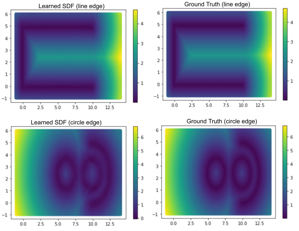
Our goal is to learn a function that maps a coordinate of a query point \((x,y) \in \mathbb{R^2}\) to a signed distance in \(\mathbb{R}\) from \((x,y)\) to the surface. The output of this function is positive if \((x,y)\) is outside the surface, negative if \((x,y)\) is enclosed by the suface, and zero if \((x,y)\) lies on the surface. Thus, our neural network is defined as \(f: \mathbb{R} ^2 \to \mathbb{R}\). For Figure 1, we learned two neural networks, the first network maps \((x,y)\) to its distance from the line edge, and the second network maps this point to its distance for the circle edge. For this task, we use a Decoder network (multi-layer perceptron, MLP), and optimize it using a gradient descent until convergence. Our dataset was created from a grid with appropriate dimensions, as these are our 2D points. Then, for each point in the grid, we calculate its distance from the line edge and the circle edge.
We compare the image from the learned SDF and the ground truth in Figure 2. It clearly shows that we can overfit and learn both the two networks for line and circle edges.

Reconstruction
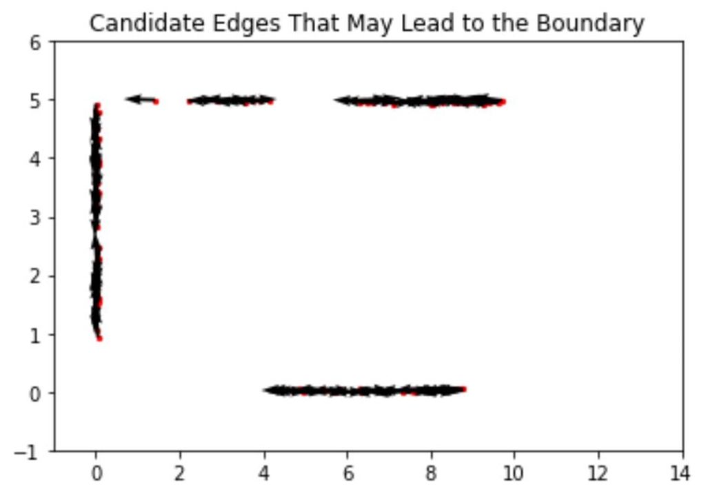
After obtaining the learned line SDF model, we need to analytically recover the edges and arcs. To define an edge, we need nothing but a starting point, a direction, and a length. So, we begin the recovery by randomly seeding thousands of points and assigning each point a random direction. Furthermore, we can only accept those points with their associated values in SDF to be close to zero (see Figure 3), which enhances the success rate of finding an edge as a part of the shape boundary.

Then, we need to tell which lines are more likely to be the ones that define the boundary of our CAD shape and reject the ones that are unlikely to be on the boundary. To guarantee a fair selection, we need to fix the length of the randomly generated edges and pick the ones whose line integral of the learned line SDF is small enough. Moreover, to save more time, we approximate the integral by a finite sum, where we sum up the SDF value assumed by a fixed number of sample points along every edge. Stopping here, we have a pool of edge boundary candidates. We visualize them in terms of their starting points and direction using a quiver plot in Figure 4.

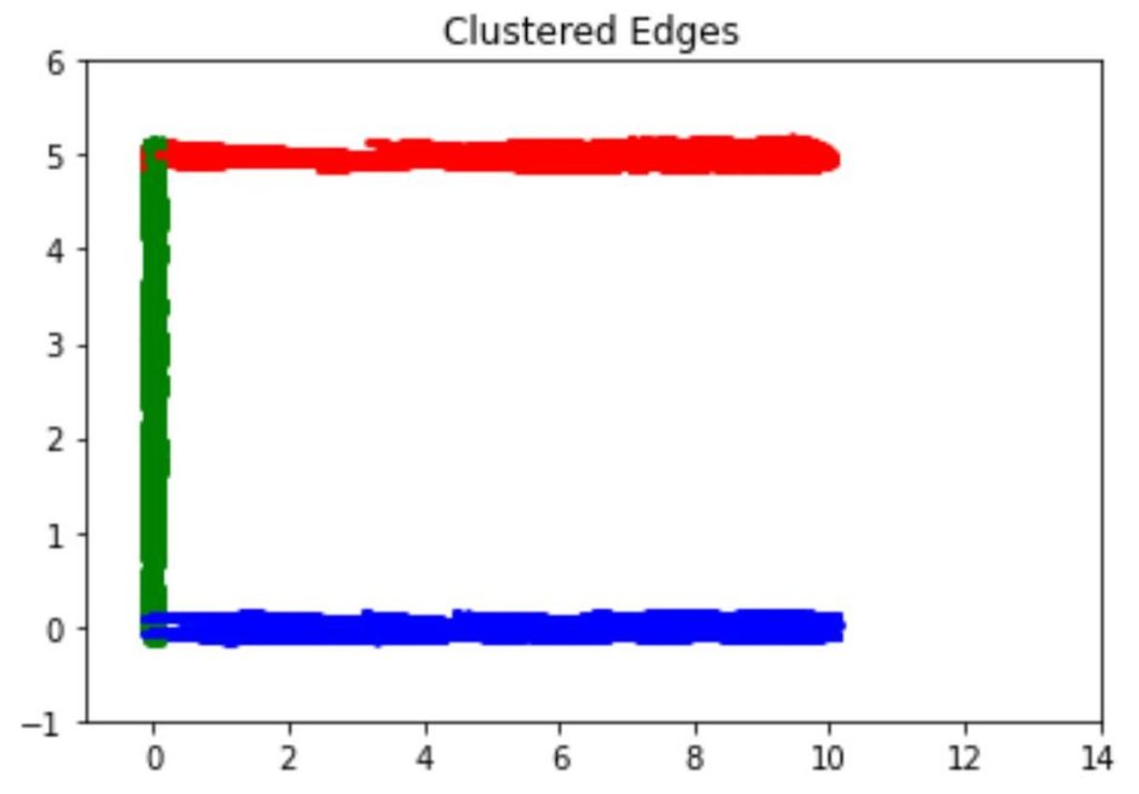
In the next step, we want to extend the candidate edges as long as possible, as our goal is to reconstruct the whole boundary. The extension ends once the SDF value of some extended point exceeds some threshold. After the extension, we cluster the extended edges using the mean shift algorithm. We adopt this clustering algorithm since it does not need to pre-determine the number of clusters. As shown in Figure 5, the algorithm successfully predicts the correct number of edge clusters after carefully tuning the parameters.

Finally, we want to extract the lines that best define the shape boundary. As we set a threshold in the extension process, we simply need to choose the longest edge from each cluster and name it a boundary edge. The three boundary edges in our example, one in each color, appear in Figure 6.

Results
To sum up, during the project’s two-week active period, we managed to complete the following items:
- We set up a neural network to learn multiple SDFs. The model learns the SDF for edge and arc components on the boundary of a 2D input shape.
- We developed and implemented a sequence of procedures to reconstruct the lines from the trained line SDF model.
Future Work
Even though we showed the results we achieved during the two weeks, there are more things to improve in the future. First of all, we need to reconstruct the arcs in 2D and ensure the whole procedure to be successful in more complicated 2D geometries. Second, we would like to generalize the whole process to 3D. More importantly, we are interested in establishing a way to smoothly and continuously characterize the shape transfer after the reconstruction. Finally, we need to transfer the continuous shape representation back to a CAD geometry.