by Denisse Garnica and Tiago Fernandes
In industry CAD (Computer-Aided Design) representation for 3D models is very used, and it is estimated that about 80% of overall analysis time is devoted to mesh generation in the automotive, aerospace and shipbuilding industries. But, the geometric approximation can lead to accuracy problems and the construction of the finite element geometry is costly, time-consuming and creates inaccuracies.
Isogeometric Analysis (IGA) is a technique that integrates FEA (Finite Element Analysis) into CAD (Computer-Aided Design) models, enabling the model to be designed and tested using the same domain representation. IGA is based on NURBS (Non-Uniformal RAtional B-Splines) a standard technology employed in CAD systems. One of the benefits of using IGA is that there is no approximation error, as the model representation is exact, unlike conventional FEA approaches, which need to discretize the model to perform the simulations.
For our week 4 project we followed the pipeline described in Yuxuan Yu’s paper [1], to convert conventional triangle meshes into a spline based geometry, which is ready for IGA, and we ran some simulations to test it.
HexGen and Hex2Spline Pipeline
The general pipeline consists of two parts: the HexGen, which transforms a CAD Model into a All-Hex Mesh, and the Hex2Spline, which transforms the All-Hex Mesh into a Volumetric Spline, ready for IGA. The code can be found here GitHub – SGI-2022/HexDom-IGApipeline.

Following the pipeline
For testing the pipeline, we reproduced the steps with our own models. LS-prepost was used to visualize and edit the 3D models. We started with two surface triangle mesh:

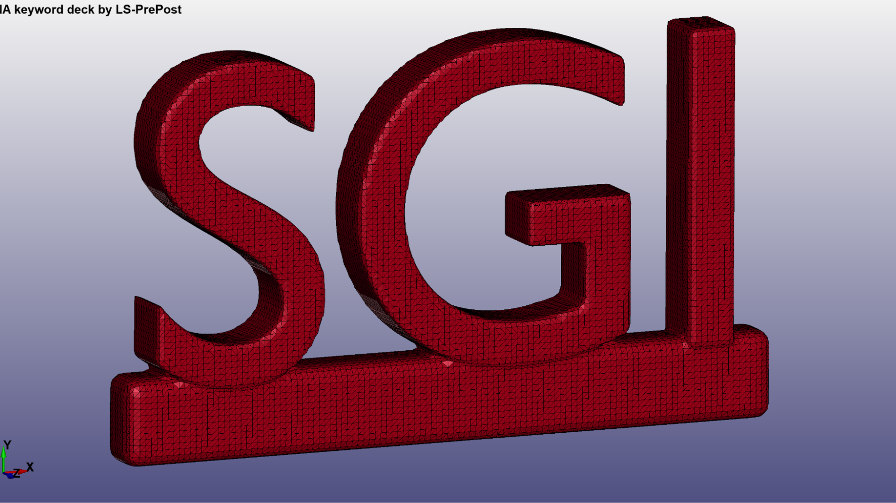
The first step of the pipeline is using a surface segmentation algorithm based on CVT (Centroidal Voronoi Tessellation), using the Segmentation.exe script. It was used to segment the triangle mesh into 6 regions, one for each of the three principal normal vectors and their opposite normals (±𝑋, ±𝑌, ±𝑍).

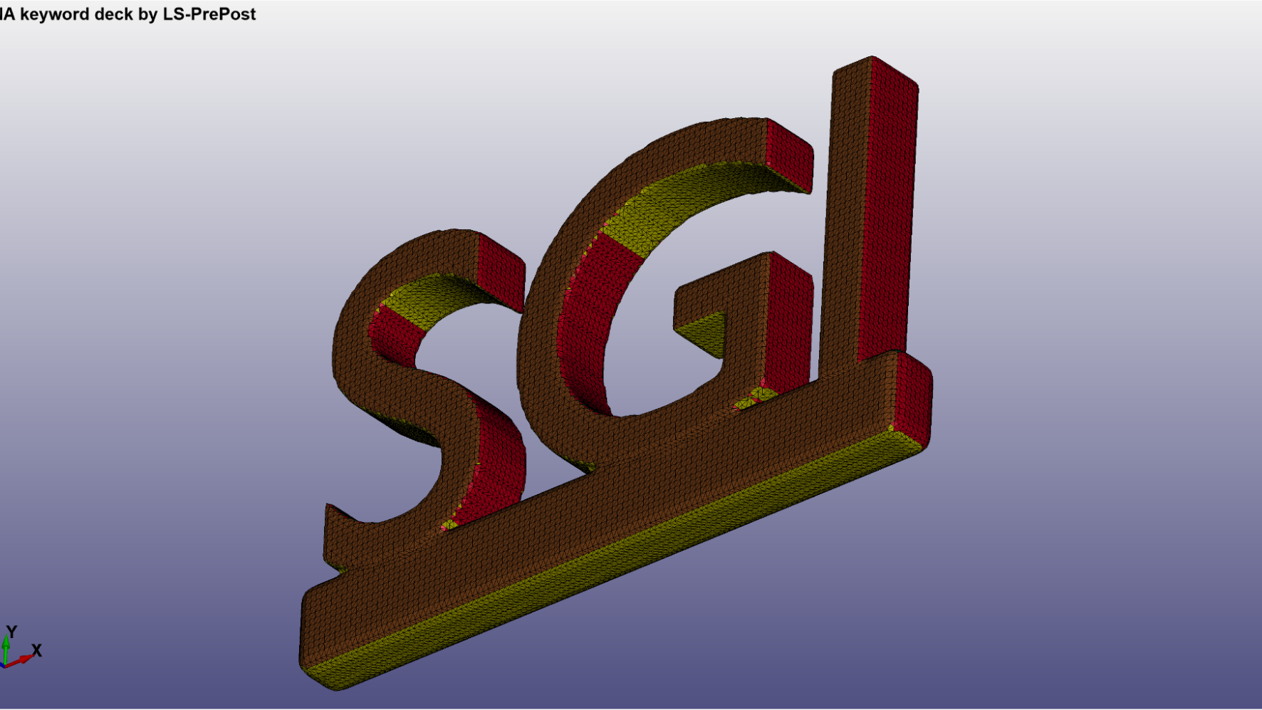
The initial segmentation only generates 6 clusters, and for more complex shapes we need a better segmentation to later build a polycube structure. Therefore, a more detailed segmentation is done, trying to better divide the mesh into regions that can be represented by polycubes. This step is done manually.

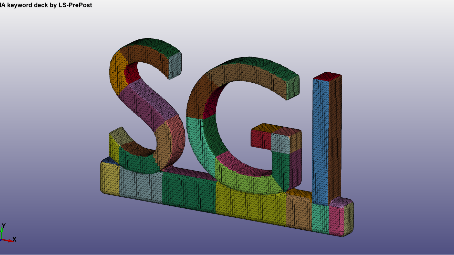
Now it is clearly visible which are the faces for the polycube structure. We can now apply a linearization operation on the segmentation, using the Polycube.exe script.

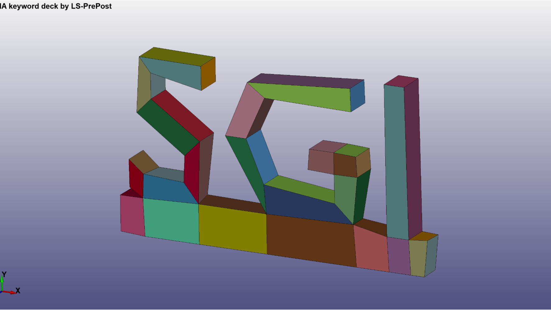
After that, we join the faces to create the cubes and finally have our polycube structure. This step is also done manually. The image in the right represents the cubes decreased in volume, for better visualization.


Then we want to build a parametric mapping between polycube and CAD model, which takes as input the triangle mesh and the polycube structure, to create an all-hex mesh. For that, we use the ParametricMapping.exe script.

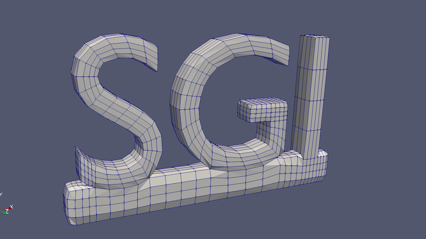
And in the last step, we use the Hex2Spline.exe script to generate the splines.

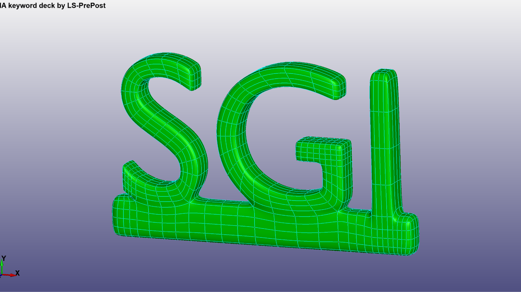
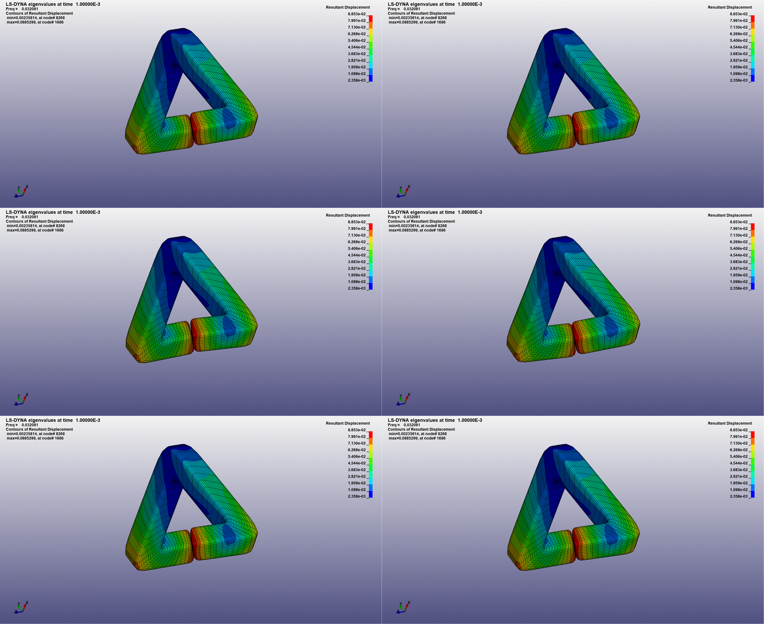
For testing the Splines, we performed a Modal Analysis (simple eigenvalue problem) in each of them, using the LS-DYNA simulator. An example for a specific displacement can be seen below:

Improvements for the pipeline
The pipeline used still have two manual steps: the segmentation of the mesh, and building the polycube structure given the linear surface segmentation. During the week, we thought and discussed some possible approaches to automate the second step. Given the external faces of the polycube structure, we need to recover the volumetric information. We came up with a simple approach using graphs, representing the polycubes as vertices, the internal faces as edges, and using the external faces to build the connectivity between the polycubes.
Although, this approach doesn’t solve all the cases, for example, when a polycube consists mostly of internal faces, and are not uniquely determined. And even if we automated this step, the manual segmentation process still is a huge bottleneck in the pipeline. One solution to the problem would be generating the polycube structure directly from the mesh, without the need of a segmentation, but it’s a hard problem to automatically build a structure that doesn’t have a big amount of polycubes and still represents well the geometry and topology of the mesh.