Categories
Research

Research and Production for Games

Visualizing and Evaluating Skin Weight Transfer

By Shannon Cudworth

My goal for this project was to implement visualization methods that help artists gauge the accuracy of skin weight transfer methods, which takes the skin weights from an already rigged mesh, and assigns the correct weights to the target mesh. I compared two different weight transfer methods. First, Maya’s built-in copySkinWeights: which takes a vertex on the unrigged mesh, finds the closest point on the source mesh, and interpolates the weights at that point to determine the weights at the vertex. Next, a method developed by EpicGames, which copies the weights from the source mesh that have a high-confidence correspondence. For the remaining vertices, it computes the weights by interpolating from the transferred high-confidence weights.

To begin, I downloaded a character with an animation from Mixamo and imported it into Maya. In my first pass comparison, I unbound the shirt from the character, and then rebound it using Maya’s copySkinWeights and EpicGames’ Weight Inpaint method. Below is a playblast of each character. Notice that with the copySkinWeights there is a jagged concave area in the upper back region, while with the Weight Inpaint method, that area is smooth.

Now, I wanted to develop a method to visually compare the two algorithms. I created a heatmap using the error formula.

Expanding on the previous idea, I wanted to develop a dynamic heat map that shows the areas with the highest deformation error over the entire animation. I created a node that took the display/method mesh and reference mesh as inputs, and then took the 3D vertex position of each of the meshes. To calculate the deformation error, I calculated the Euclidean distance between the 3D vertex positions of the method I was evaluating and the 3D vertex position of the original mesh. This is calculated with:

di(t)=‖ximethod(t)−xioriginal(t)‖2d_i(t) = \left\| x_i^{\mathrm{method}}(t) – x_i^{\mathrm{original}}(t) \right\|_2

where i represents the ith vertex of the matrix, ximethod(t)x_i^{\mathrm{method}}(t) is the 3D position of vertex i on the method mesh at frame t, xioriginal(t)x_i^{\mathrm{original}}(t) is the 3D position of vertex i on the original method at frame t.

To construct the heat map, we normalize and clamp with:

d~i(t)=min⁡(di(t)c,1)\tilde{d}_i(t) = \min\left(\frac{d_i(t)}{c},\,1\right)

where c is the maximum deformation distance.

We then mapped the errors to colors and wrote all vertex colors to the output mesh with setVertexColors(). We then have our finished output mesh with our desired heatmap. As the animation changes, the input meshes will change, causing the heatmap to update with each frame. This was packaged into a UI for easier use.

Here is the heat map applied to a shirt that was rigged using Maya’s copySkinWeights:

Here is the heat map applied to a shirt that was rigged using EpicGames Inpaint method:

Reference: EpicGames Inpaint Method

TextDeformer: How can words shape the (virtual) world

Researched by: José Pablo Soto Sánchez

Introduction

Imagine handing a sculptor a block of clay and, instead of tools, just a sentence: “make this a giraffe.” No reference photos, no measurements, just words, and the expectation that the clay reshapes itself to match. That’s roughly what TextDeformer (Gao et al., SIGGRAPH 2023) does to a 3D mesh: given a source shape and a target text prompt, it deforms the geometry until a frozen vision-language model agrees that the render looks like the prompt.

What makes this interesting isn’t just the result it’s used purely as a differentiable critic. The actual “learning” happens directly on the geometry: a set of per-triangle Jacobian matrices gets optimized by gradient descent, the same way you’d optimize the weights of a network, except here the “weights” are literally how each triangle is allowed to stretch and rotate.

This post walks through reproducing the official TextDeformer codebase end-to-end on consumer hardware, the math that makes text-to-geometry gradients possible at all, and the specific things that broke along the way and how they got fixed.

Background

A few terms are worth pinning down before the method section, since the pipeline sits at the intersection of graphics and vision-language modeling:

TermPlain-language definition
CLIPA frozen, pretrained model that embeds images and text into the same vector space, so cosine similarity between an image embedding and a text embedding measures “how well does this image match this caption.”
Differentiable renderingTurning a 3D mesh + camera into a 2D image using operations (rasterization, shading) that support backpropagation, so pixel-level loss can flow gradients back to vertex positions.
Jacobian (per-triangle)A 3×3 matrix describing how a single triangle is locally stretched/rotated relative to its original shape. TextDeformer optimizes one of these per face, directly.
Poisson mesh reconstructionGiven a target Jacobian per triangle, solving a linear system to recover the vertex positions whose actual local deformation best matches those targets, in a least-squares sense.
Cotangent LaplacianA sparse matrix built from mesh geometry that encodes how each vertex relates to its neighbors; it’s the operator at the center of the Poisson solve.
ViT patchA Vision Transformer splits an image into fixed-size square tiles (“patches”) and treats each one like a token — patch size determines how fine-grained the model’s spatial resolution is.

Method

CLIP-guided losses

The core signal is cosine similarity between a rendered image’s CLIP embedding and the target text’s CLIP embedding:

ℒΔclip=−cos⁡(fimg(I^)−fimg(Ibase),  ftext(target)−ftext(base))\mathcal{L}_{\Delta\text{clip}} = -\cos\big(f_{\text{img}}(\hat{I}) – f_{\text{img}}(I_{\text{base}}),\ \ f_{\text{text}}(\text{target}) – f_{\text{text}}(\text{base})\big)

But optimizing this alone tends to drift toward whatever image maximizes similarity to the prompt, not necessarily a smooth deformation of the source shape. TextDeformer adds a delta-CLIP term that instead matches the change in image embedding against the *change* in text embedding, relative to a fixed base render/prompt (e.g. “a cow”):

ℒclip=−cos⁡(fimg(I^), ftext(“a giraffe”))\mathcal{L}_{\text{clip}} = -\cos\big(f_{\text{img}}(\hat{I}),\ f_{\text{text}}(\text{“a giraffe”})\big)

This directional formulation (used in prior CLIP-guided editing work) keeps the deformation anchored to the source identity instead of collapsing onto an unrelated “giraffe-like” blob.

Per-triangle Jacobians and the Poisson solve

This is the part that replaces a neural decoder entirely. Given the mesh’s gradient operator GG (one 3×3 block per face) and a diagonal mass matrix MM of face areas, the cotangent Laplacian is built as:

L=G⊤MGL = G^\top M G

LL has a one-dimensional null space (constant functions), so the implementation drops the first row/column to pin a single vertex before it’s usable for Cholesky factorization. To go from optimized per-face Jacobians JJ back to vertex positions vv, the code solves the normal equations of a least-squares problem — find the vv whose actual gradient GvGv is as close as possible to the target Jacobians JJ, weighted by face area:

v∗=arg⁡minv⁡‖Gv−J‖M2⟹Lv=G⊤MJv^* = \arg\min_v \| Gv – J \|_M^2 \quad\Longrightarrow\quad L\, v = G^\top M J

That linear system is factorized once per mesh with a sparse Cholesky solver (`cholespy`, GPU-resident) and re-solved every optimization step as JJ changes — cheap after the one-time factorization. A Jacobian regularization term, ‖J−I‖2\| J – I \|^2, keeps triangles from stretching into degenerate shapes.

Rendering and camera augmentation

Each step, a batch of random cameras (elevation drawn from a Beta distribution, azimuth uniform over 360°, random distance/FOV/lighting/background) renders the current mesh via nvdiffrast‘s differentiable rasterizer. Randomizing viewpoint and lighting every step is what prevents the optimizer from exploiting a single “good” camera angle instead of actually deforming the geometry.

Patch-level consistency loss

A second, separate CLIP ViT is used only for its intermediate patch features (via forward hooks on each transformer block). For pairs of cameras within the same batch that are close in elevation/azimuth, the patches that project to the same 3D vertex are compared — encouraging the same surface point to look consistent from nearby viewpoints, which curbs the multi-view incoherence (“Janus-face”-style artifacts) common to CLIP-guided 3D optimization.

Implementation

Getting the reference implementation running at all. 

The repo pins specific commits for nvdiffrast and installs igl unpinned via conda-forge. The unpinned igl immediately caused a break: igl.random_points_on_mesh  in  MeshProcessor.py expected a 2-tuple return (bary, face_idx), but the installed libigl build now returns a 3-tuple (B, FI, P). Fixed by unpacking a third, unused value — a reminder that “no version pin” in a 2023 paper repo means the API surface has already drifted.

Fighting the GPU context, not the geometry. 

The next failure had nothing to do with the algorithm:  dr.RasterizeGLContext() threw cudaGraphicsGLRegisterBuffer (CUDA error 304, cudaErrorOperatingSystem) on first render. [VERIFY: root cause inferred from the error code and hybrid-GPU laptop symptoms, not confirmed via driver-level logs] — the working hypothesis is that Windows was creating the OpenGL context on the integrated GPU while CUDA ran on the discrete GPU, breaking the CUDA↔GL interop nvdiffrast relies on. The pinned nvdiffrast commit doesn’t expose the pure-CUDA rasterizer (RasterizeCudaContext isn’t present in this build), so the fix was OS-level: explicitly forcing the Python process to the discrete GPU in Windows’ graphics settings, rather than a code change.

Finding the actual VRAM ceiling. 

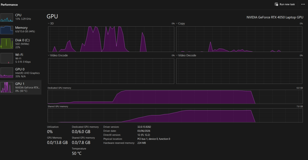
With rendering working, the default config (batch_size=25, train_res=512) ran out of memory on a 6 GB laptop GPU (RTX 4050) partway through the first step. The batch dimension and the render resolution both scale memory close to linearly, so both got reduced (batch_size=4, train_res=256) until a full 2,500-step run completed without OOM. This became the baseline configuration for every later experiment.
Swapping CLIP backbones without breaking assumptions baked into the code. 

clip_model and consistency_clip_model are independently configurable, but the consistency-loss implementation (utilities/clip_spatial.py) hardcodes assumptions that only hold for the “Base” ViT variants: a for i in range(12) loop over transformer blocks (ViT-L/14 has 24), and an assertion that the patch stride evenly divides the patch size (ViT-L/14‘s 14px patch isn’t divisible by the default stride of 8, unlike 32px/16px). RN50 — a convolutional backbone — can’t be used for the consistency loss at all, since that code depends on ViT-style patch tokens that a ResNet simply doesn’t produce. ViT-B/32, ViT-B/16, and RN50 (as the primary loss only) were compared under an identical seed/mesh/prompt to keep the comparison controlled; ViT-B/32 was kept as the default going forward, primarily because it fit the VRAM budget without further code changes.

Debugging a mesh, not the code.

A custom tuna.obj mesh failed with CHOLMOD: not positive definite inside the Cholesky factorization. The Laplacian LL is only positive-definite after pinning one null-space direction — which is correct for a single connected mesh, but insufficient if the mesh has multiple disconnected components (each contributes its own null direction). The tuna model’s eyes turned out to be separate, unwelded geometry. Diagnosing this required leaving the codebase entirely and going into Maya: using Mesh → Separate to count connected shells, Combine + Merge (vertex welding by distance) to attempt reattachment, and re-running Separate as the verification step (if it can no longer split the mesh, it’s genuinely one piece). Welding never fully closed the gap without visibly displacing the eyes during remeshing, so the pragmatic fix was deleting the eye geometry outright, producing tunaNoEyes.obj — a reminder that not every mesh bug is worth solving at the mesh level when the pipeline’s actual requirement (single connected component) can be satisfied more simply.

Stale caches and unattended runs.

MeshProcessor caches differential operators and Jacobian .npz files under <output_path>/tmp/ and silently reuses them if present — convenient for resuming, dangerous if the source mesh changes but the output path doesn’t: a later run against a re-exported (different vertex count) tuna.obj crashed in a sparse matrix multiply because the cached operators no longer matched. Once that class of bug was understood, a small driver script (run_batch.py) was written to chain multiple mesh/prompt runs sequentially — the single 6 GB GPU rules out any parallelism — each with a fresh output directory and its own log file, so a several-hour unattended batch could run overnight without one failed run silently corrupting the next.

Results

Five source→target pairs were run to completion on the final configuration (batch_size=4, train_res=256, ViT-B/32, single RTX 4050 Laptop GPU):

Source → TargetStepsWall-clock
cow → giraffe (spot.obj)5,0001h 14m
fish → shark10,0002h 37m
eiffel tower → rocket10,0003h 21m
tuna → shark (tunaNoEyes.obj, remeshed)10,0002h 33m
guitar → axe6009m 39s

Per-step cost stayed in a fairly narrow band (~0.89–1.2 s/step) across meshes of similar triangle count, and scaled with batch_size × train_res as expected from the rendering cost analysis above — the guitar → axe run at 600 steps was deliberately short (~10 minutes) as a fast-iteration sanity check rather than a converged result, and looks correspondingly less refined than the 10k-step runs.

Future Work

Validate mesh topology before the Poisson solve, not during it. 

The tuna.obj failure surfaced as a Cholesky exception deep inside training, three layers of traceback away from the actual cause (disconnected components). A pre-flight check — counting connected components with igl and failing fast with a clear message before any GPU work starts — would turn a confusing runtime crash into an immediate, actionable one, and is a small, self-contained addition to MeshProcessor.py.

Generalize the consistency-loss encoder beyond the “Base” ViT assumption. 

The hardcoded 12-layer loop and stride-divisibility requirement in clip_spatial.py make ViT-L/14 unusable for the consistency loss without a code change, and rule out testing community-trained checkpoints (e.g. LAION’s ViT-B-32 retrained on LAION-2B via open_clip) that share the same architecture but arrive through a different loading path than OpenAI’s clip package. Both are architecture-family limitations, not fundamental ones — worth fixing before running a broader backbone ablation.

Reference

https://threedle.github.io/TextDeformer

ShapeFlow: Morphing Between 3D Shapes

We also explored a method for morphing one 3D shape into another target 3D shape. We worked with ShapeFlow, a neural network that learns to deform an existing 3D shape into another through a continuous flow field. Given latent space encodings of a source and target shape, the model outputs a velocity field describing how each point on the source should move to arrive at the target. Because the flow is continuous and (under the right conditions) bijective, the resulting deformation is guaranteed to be free of self-intersections, and can optionally preserve volume. Both of these properties can be desirable for artists working with meshes, which makes ShapeFlow attractive for toolification.

The Model

ShapeFlow’s creators frame the deformation of source shape XiX_i into target shape XjX_j as an advection process–the movement of a conserved property through fluid flow. Each point xx on the source is carried along a flow field f(x,t)f(x,t) over an interpolation parameter t∈[0,1]t\in[0,1]. Then, the points of the deformed source shape ϕij\phi_{ij} are described as:

Φij(x)=x(1), where x(t)=x(0)+∫0tfij(x(τ),τ)dτ\Phi_{ij}(x)=x(1) , \text{ where } x(t)=x(0)+\int_0^t f_{ij}(x(\tau),\tau)\;d\tau

Training seeks the mapping Φθij\Phi_{\theta}^{ij} that minimizes the symmetric Chamfer distance between the deformed source and the target:

minθC(Φθij(Xi),Xj)+C(Xi,Φθji(Xj))min_\theta \quad C(\Phi_{\theta}^{ij}(X_i), X_j) + C(X_i, \Phi_{\theta}^{ji}(X_j))

So the output of ShapeFlow is this flow field or mapping Φθij\Phi_{\theta}^{ij} that describes how each point on the source shape should advect in order for the source to become the target shape. How are the inputs to ShapeFlow created? What do we feed to the model?

Recall, we said that the input to ShapeFlow is the pair of latent space encodings from the source and target shapes. For our implementation, we use an encoder that maps a mesh’s vertices to a latent space encoding using a single forward pass. The encoder is trained jointly with the deformer model, using the same Chamfer distance loss, so it learns to produce encodings that are useful for conditioning the flow field.

The Toolification

Our goal was to implement ShapeFlow as a Maya plug-in for artists’ use in stylization and retopology of one mesh to another. To increase usability, we added blendshapes between the source mesh and the deformed source mesh by extracting and exporting intermediate results along the deformation path (sampling ϕij(x)ϕ_{ij}(x) at intermediate values of tt). This way, an artist can scrub through the flow and select whichever stage best fits their needs.

Future Exploration & Improvement

While implementing ShapeFlow as a Maya tool for artists, we ran into some areas of exploration for the performance of the tool. With more time we would have done more experimenting and development to ensure the model’s capabilities are consistent and high-performing for our desired use cases. On the SGI timeline we ultimately decided to balance exploration and execution and forge ahead with building out the tool while noting areas for improvement:

  • Initialization Sensitivity: Since the initialization of the model weights are random, results can vary widely based on whether one initialization was “good” for the specific meshes being used.
  • Loss Function Limitations: One of the use cases we wanted to develop ShapeFlow for was to create intermediate expressions for a given face mesh with certain extreme expressions. However, when morphing between meshes that differ only in a small region–for example puckered lips vs. a neutral expression–the region may be too small to affect the Chamfer distance loss during optimization. Other loss functions are worth evaluating for these cases.
  • Pretraining: If there are certain use cases (classes of objects, faces) that ShapeFlow will be used for, it might be beneficial to do pretraining on those types of shapes. Currently, our tool trains the deformer model from scratch every time. (This is also why the initialization sensitivity affects the results so strongly.) As a result, the model either will take an extremely long time with an appropriate amount of training iterations, or be used after a lower number of training iterations with reduced fidelity.

We did some manual tuning to get workable results on our test meshes, but making this robust enough for an artist’s workflow requires additional experimentation, testing, and development.

Results

Below is a video demonstrating the Maya tool workflow. For the sake of time, in the video the model is only trained for 200 iterations (very low), which is one source of the poor or unfinished-looking output flow.

Below is an image showing how ShapeFlow can be used to produce a blend of two meshes. The ShapeFlow output (middle) is result of Toilet 1 (left) morphing into toilet 2 (right).

Reference

ShapeFlow

Categories
Research

Exploring Dependence Between Curvature and Heat Diffusion on a Mesh

By Shannon Cudworth, Mentors: Alek Fröhlich and Daniel Perazzo

Introduction

The goal of the project was to study statistical dependence from geometric perspective, where we define two random variables X, Y are defined on a surface ℳ\mathcal{M}, rather than in a Euclidean space. Specifically, we explore whether heat diffusion across a surface is dependent on the local curvature.

To study this relationship, we randomly sample a triangle face from a mesh and then construct one heat diffusion variable and one curvature variable for this sampled face. The former variable was defined using the Laplace-Beltrami operator, and for the latter variable we used the mean curvature value at the sampled face’s barycenter. We then employed the Hilbert–Schmidt Independence Criterion (HSIC) to investigate if faces with similar heat diffusion also have similar curvature.

To implement, we first sample faces with a probability proportional to their area, to avoid oversampling smaller triangles. After constructing the two aforementioned variables, we make curvature and heat kernel matrices to describe pairwise curvature and heat similarity, run a permutation test, and repeat for various sample sizes to estimate the power of the sample HSIC test.

Constructing the Heat Diffusion Variable

To approximate heat diffusion, we’re going to use the Laplace-Beltrami operator. For this, we need the cotangent Laplacian and mass matrix.

Cotangent Laplacian: A discrete approximation of the Laplace-Beltrami operator, used on triangle meshes. We define this matrix using the piecewise function:

Lij={−12(cot⁡αij+cot⁡βij),i≠j, (i,j)∈E,∑k∈𝒩(i)12(cot⁡αik+cot⁡βik),i=j,0,otherwise.L_{ij} = \begin{cases} -\frac{1}{2}\left(\cot\alpha_{ij}+\cot\beta_{ij}\right), & i\neq j,\ (i,j)\in E,\\ \sum_{k\in\mathcal{N}(i)} \frac{1}{2}\left(\cot\alpha_{ik}+\cot\beta_{ik}\right), & i=j,\\ 0, & \text{otherwise.} \end{cases}

Where αij\alpha_{ij} and βij\beta_{ij} are opposite angles for the edge (ij), and N(i) is the set of neighboring vertices to vertex i.

Mass Matrix: Represents how much of the mesh’s surface area is associated with each individual vertex, and was defined using gpy toolbox.

With both of these components, we can understand the geometric variation of the mesh’s surface (through the Laplacian), and how much the variation contributes to the overall surface area of the mesh (though the Mass Matrix).

To actually approximate the heat diffusion over the area, we need to solve the eigenvalue problem:

Lϕi=λiMϕiL\phi_i = \lambda_iM\phi_i

where L is the cotangent laplacian, M is the mass matrix, ϕi\phi_i is the ith eigenvector, and λi\lambda_i is the corresponding ith eigenvalue.

Using Scipy, we solve for the first 100 eigenvector-eigenvalue pairs, which represents the 100 smoothest solutions to the equation above. The eigenvector defines a basis function over the mesh vertices, and the eigenvalue is the rate of decay under heat diffusion.

Now, to construct our random variable X, we must recall that we have sampled a random face of the triangle mesh, and we have two arrays eigenvectors and eigenvalues, where:

eigenvectors[i]
eigenvalues[i]

returns the first 100 eigenvectors and eigenvalues at vertex i of the mesh. To utilize these arrays, we must directly evaluate the eigenvalue problem at the sampled face’s barycenter. Then for the sampled face with vertices i,j,k we calculate:

(eigenvectors[i] + eigenvectors[j] + eigenvectors[k]) / 3

which gives us a vector of the form:

[ϕ1(bi)ϕ2(bi)⋮ϕ100(bi)]\begin{bmatrix} \phi_1(b_i) \\ \phi_2(b_i) \\ \vdots \\ \phi_{100}(b_i) \end{bmatrix}

where bib_i is the barycenter of the ith sampled face.

Then using the respective eigenvalue, we can construct a random variable XiX_i that represents the heat diffusion from barycenter of the ith sampled face with:

Xi=[e−tλ1/2ϕ1(bi)e−tλ2/2ϕ2(bi)⋮e−tλ100/2ϕ100(bi)].X_i = \begin{bmatrix} e^{-t\lambda_1/2}\phi_1(b_i) \\ e^{-t\lambda_2/2}\phi_2(b_i) \\ \vdots \\ e^{-t\lambda_{100}/2}\phi_{100}(b_i) \end{bmatrix}.
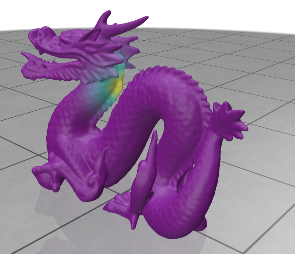
Figure: Heat diffusion from the barycenter of the sampled face on the dragon mesh

Constructing the Curvature Variable

To construct the curvature variable, we calculate the mean curvature at each of the sampled face’s three vertices. Using libigl’s principal curvature value function, we return k1, k2,k_1, \space k_2, the maximum and minimum curvature values at a vertex, respectively. We can then calculate the mean curvature value, defined as:

H=(k1+k2)2H = \frac{(k_1 + k_2)}{2}

If the mean curvature is small or 0, we can interpret either a locally flat surface, or a saddle structure where k1k_1 and k2k_2 cancel each other out. A larger mean curvature indicates bending.

Then for the ith sampled face with vertices i,j,k, we can construct the random variable YiY_i, which will calculate the curvature at the face’s barycenter, defined as:

Yi=H(bi)=(Hi+Hj+Hk)3Y_i = H(b_i) = \frac{(H_i + H_j + H_k )}{3}

where Hi, Hj, HkH_i,\space H_j, \space H_k are the mean curvature values at vertex i, j, k, and H(bi)H(b_i) is the mean curvature at the barycenter of the ith sampled face.

Kernels

To check independence between our two random variables X and Y, we must construct kernel matrices, which will measure the similarity between pairs Xi, XjX_i, \space X_j and Yi, YjY_i, \space Y_j (Schrab 19).

X variable: By construction of the laplacian, we can calculate the heat kernel KXK_X by:

KX=XXTK_X = XX^T

By definition:

Xi=[e−tλ1/2ϕ1(bi)e−tλ2/2ϕ2(bi)⋮e−tλ100/2ϕ100(bi)].X_i = \begin{bmatrix} e^{-t\lambda_1/2}\phi_1(b_i) \\ e^{-t\lambda_2/2}\phi_2(b_i) \\ \vdots \\ e^{-t\lambda_{100}/2}\phi_{100}(b_i) \end{bmatrix}.

Then we can say for any i,j:

XiXj⊤=∑ℓ=1100(e−tλℓ/2ϕℓ(bi))(e−tλℓ/2ϕℓ(bj))X_{i}X_{j}^{\top} = \sum_{\ell=1}^{100} \left( e^{-t\lambda_\ell/2}\phi_\ell(b_i) \right) \left( e^{-t\lambda_\ell/2}\phi_\ell(b_j) \right)

Then,

XiXj⊤=∑ℓ=1100e−tλℓϕℓ(bi)ϕℓ(bj)X_{i}X_{j}^{\top} = \sum_{\ell=1}^{100} e^{-t\lambda_\ell}\phi_\ell(b_i) \phi_\ell(b_j)

which is the heat kernel formula (Mostowsky et al.).

Y variable: Unlike the heat diffusion variable X, we need to do a few more calculations to compute the curvature kernel KYK_Y, which we will do by using the Gaussian Kernel formula.

First, we define σY\sigma_Y, which represents the median pairwise distance for each Yi, YjY_i,\space Y_j pair. Then we can calculate the kernel KYK_Y using the formula, for each i,j pair:

KY(i,j)=exp(−||Yi−Yj||22σY2)K_Y(i,j) = exp(-\frac{||Y_i – Y_j||^2}{2\sigma_Y^2})

If KX, KYK_X, \space K_Y are large, then it follows that the ith and jth sampled faces have similar diffusion or similar curvature, respectively. Rather, if the kernels are small, then we can say the ith and jth sampled faces have different diffusion or curvature, respectively.

Hilbert-Schmidt Independence Criterion (HSIC)

The kernel matrices KX,KYK_X, K_Y allow us to determine if there are any similarities between pairs Xi, XjX_i, \space X_j or Yi,YjY_i, Y_j. Now, we want to examine that if pair Xi,XjX_i, X_j are similar, if it is true that pair Yi,YjY_i, Y_j are similar as well. To acheive this, we compute the sample HSIC.

To ensure valid comparability between variables, we first make a centering matrix, defined as:

H=Inxn−1nJnxnH = I_{nxn} – \frac{1}{n}J_{nxn}

where JnxnJ_{nxn} is a matrix of all ones.

We can then define the centered kernels for X and Y as:

KXC=HKxH KYC=HKYHK_{XC} = HK_xH \\\\\\\\\\\\\ K_{YC} = HK_YH

Then, by definition,

HSIC(KX,KY)=1(n−1)2tr(KXCKYC)HSIC(K_X,K_Y) = \frac{1}{(n-1)^2}tr(K_{XC}K_{YC})

Here, a large sample HSIC value indicates dependence between heat diffusion and curvature (Schrab 25).

Permutation Testing and Power

One sample HSIC value isn’t enough to statistically determine whether or not X, Y have dependence. So, we must undergo a permutation test. To start, we define a null and alternative hypothesis:

H0:X,Y are independentHA:X,Y are dependentH_0: X, Y \space are \space independent \\ H_A: X, Y \space are \space dependent

Our goal for this test is to simulate under the null hypothesis, and then see how likely our originally observed sample HSIC is to occur in those conditions. We permute the order of KYK_Y, recompute the sample HSIC, and repeat 200 times to create the null distribution. We then use the observed sample HSIC to calculate a p-value, which indicates whether or not we should reject or fail to reject the null hypothesis.

Taking a step further, we calculated the power of the sample HSIC test, which will give us the probability that, when X and Y are dependent, the sample HSIC will correctly detect that dependence. We do this by repeating the permutation test, and dividing the amount of times we rejected the null (p-value was less than 0.05, depending on significance level) by the total amount of retrials.

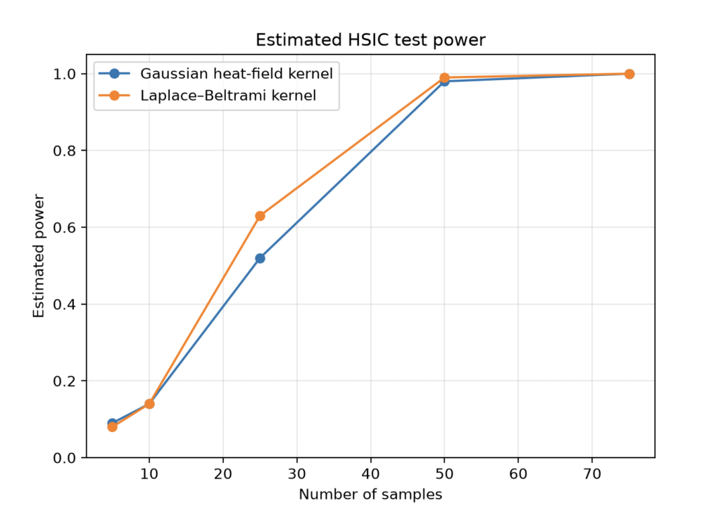
In our project, we compared the power of the sample HSIC test across sample sizes: 5, 10, 25, 50, 75, and repeated the permutation test 100 times per each sample size. We also compared the sample HSIC using the aforementioned heat diffusion kernel that was calculate with the Laplace-Beltrami operator, and another heat diffusion X variable and kernel, that was constructed using a numerical approximation and Gaussian Kernel method.

Figure: Shows the HSIC test power between random variables X,Y with a Gaussian heat diffusion kernel and Laplace-Beltrami heat diffusion kernel. Note that while the Laplace-Beltrami kernel does better for smaller samples, both converge to 1 as sample size increases.

From the figure, we can see that, as the sample size increases, the power of sample HSIC test equals 1. This means that every trial rejected the null hypothesis, and the sample HSIC test is successful at detecting dependence between heat diffusion and curvature.

Possible Extensions of the Project

I think it would be fun to compare the sample HSIC across different meshes, and maybe how quickly the power of the sample HSIC test converges to one across different meshes. We could also compare different curvature formulas with heat diffusion, or vary the time that we allow heat diffusion to occur. Or, we can explore with different variables, such as letting X represent the geodesic field from a sampled face, and compare that to curvature.

Works Cited

Schrab, Antonin. “Optimal Kernel Hypothesis Testing.” University College London, 2025.

Mostowsky, Peter, et al. “The GeometricKernels Package: Heat and Matérn Kernels for Geometric Learning on Manifolds, Meshes, and Graphs.” Journal of Machine Learning Research, vol. 26, no. 276, 2025, pp. 1–14.

odedstein. sgi-introduction-course. GitHub, https://github.com/ddecatur/sgi-introduction-course.

Categories
Research

Surface Log Maps

by Anja Milutinovic and Shannon Cudworth

Geodesics and geodesic distance

Suppose we have a curved surface M⊂ℝ3\mathbb{R}^3. If we want to measure distances or move from one point to another, Euclidean straight lines are no longer appropriate because they leave the surface. So we generalise the notion of a “straight line”, by seeking the straightest possible path that remains on the surface. This is called a geodesic.

More formally, a geodesic is a curve that locally minimizes the length L of the curve:

L(γ)=∫01‖γ′(t)‖dt,where γ′(t)∈Tγ(t)M.L(\gamma)=\int_0^1 \|\gamma'(t)\|\,dt,\quad \text{where }\gamma'(t)\in T_{\gamma(t)}M.

The geodesic distance between two points p, q M is:

dM(p,q)=infγ:[0,1]→M,γ(0)=p,γ(1)=q⁡L(γ)d_M(p,q)=\inf_{\gamma:[0,1]\to M,\,\gamma(0)=p,\,\gamma(1)=q}L(\gamma)

Exponential and logarithmics maps

Given a point p∈Mp\in M and a tangent vector v∈TpMv\in T_pM, there exists a unique geodesic γ\gamma such that γ(0)=p\gamma(0)=p and γ′(0)=v\gamma'(0)=v. Exponential map Expp⁡:TpM→M\operatorname{Exp}_p:T_pM\rightarrow M is a map that for every v∈TpMv\in T_pM gives the endpoint of the geodesic starting at p with the direction vv and length ‖v‖\|v\|. 

Then, the logarithmic map is the inverse of the exponential map,  Logp⁡:M→TpM\operatorname{Log}_p:M\rightarrow T_pM, whenever the exponential map is invertible. Logarithmic map for any given point q∈Mq\in M is a tangent vector that gives the initial direction of a geodesic starting at p and ending at q.

Combining the logarithmic map with the frame ϕp:TpM→ℝ2\phi_p:T_pM\rightarrow\mathbb{R}^2, we get 

z=ϕp∘Logp⁡z=\phi_p\circ\operatorname{Log}_p, that maps any point q on a surface into ℝ2\mathbb{R}^2.

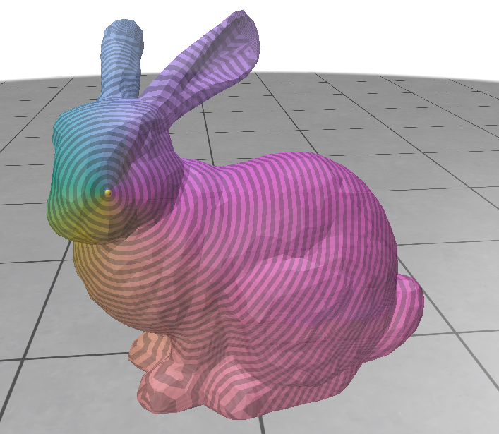
Local parameterization of the Stanford Bunny using a logarithmic map centered at a selected point.

Levi Civita connections

Given two neighboring vertices v1,v2v_1, v_2 on a discrete triangle mesh, we can define corresponding tangent vectors t1,t2,t_1, t_2, such that t1t_1and t2t_2 belong to the tangent planes at v1v_1 and v2,v_2,respectively. Since t1, t2t_1,\ t_2 lie on different tangent planes, we cannot meaningfully compare them. Our goal is to define a parallel transport, which moves one tangent vector to another tangent plane at an adjacent vertex, while minimizing rotation, known as the Levi Civita connection.

To implement the Levi Civita connection, we are given a dictionary containing all vertices with a shared edge, and the normal vector defined at every vertex viv_i. By looping over all shared edges i,ji,j, we take neighboring vertices vi,vjv_i, v_j and we index and define the normal vectors corresponding with the vertices, labeled n1n_1 and n2n_2, respectively.  We then use the normals to calculate the Rodrigues Rotation, or the rotation of a vector by a specific angle around a fixed axis. The formula to determine this rotation matrix is given by:

R=I+vx+vx2×1−cs2R = I + v_x + v_x^2 \times \frac{1-c}{s^2}

where v=n1×n2, c=n1⋅n2, s=||v||, 𝐯×=[0−v2v1v20−v0−v1v00]v = n1 \times n2,\ c = n1 \cdot n2, \ s = ||v||, \ \mathbf{v}_{\times}=\left[\begin{array}{ccc}0&-v_2&v_1\\v_2&0&-v_0\\-v_1&v_0&0\end{array}\right]

Then R approximates Levi Civita connection between adjacent tangent planes.

Connection Laplacian

After constructing the Levi Civita connection, we want to compare the tangent vectors at neighboring vertices, which is accomplished through the Connection Laplacian. As before, we loop over all vertices i,j with shared edges, and first define the cotangent weights, which are given by:

wij=12(cotαij+cotβij)w_{ij} = \frac{1}{2}(cot\alpha_{ij} + cot\beta_{ij})

where αij\alpha_{ij} and βij\beta_{ij} are the two angles opposite the edge (i, j). Now we can define the Connection Laplacian matrix, defined as:

Lij={(∑k∈N(i)wik)I,amp;i=j,−wijRji,amp;(i,j) is an edge,0,amp;otherwise. L_{ij}= \begin{cases} \left(\displaystyle\sum_{k\in N(i)} w_{ik}\right)I, &amp; i=j, \\[1.2ex] -w_{ij}R_{ji}, &amp; (i,j)\text{ is an edge}, \\[0.8ex] 0, &amp; \text{otherwise}. \end{cases}

where wijw_{ij} is the cotangent weight between vertex i and vertex j, RijR_{ij} is the Levi Civita connection between vertex i and vertex j, and N(i)N(i) is the set of adjacent vertices to vertex i. Once the Connection Laplacian is defined, we can now measure how tangent vector fields change across vertices and our mesh.

Heat Diffusion & Vector Heat Method

With the Levi Civita connection and the Connection Laplacian, we can now define the Vector Heat Method (VHM), which approximates parallel transports between arbitrary vertices on our surface.

Given a mass matrix M, a connection laplacian L, an initial vector field V, and a small time step h, we can solve the vector heat equation:

(M+hL)X=V(M + hL)X = V

where X is a vector field that approximates the parallel transport of V along the minimal geodesics.

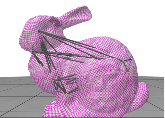
We now introduce a set of user-selected seed vertices S = { s1, ... ,sks_1,\ … \ , s_k } ⊂V. Via the VHM, we can approximate the parallel transport between any arbitrary seed vertices. Our goal is to extend this to the Affine Heat Method, which will use the VHM estimations of parallel transport between seed frames to optimize a set of tangent frames, allowing adjacent logarithmic maps to be more effectively blended.

Seed graph with optimal frames & UV offset

A single logarithmic map only provides a low-distortion parameterization around one point on the surface. To cover the entire mesh, we choose a small set of seed verticesS={s1,…,sk}⊆V,S=\{s_1,\ldots,s_k\}\subseteq V,and compute one logarithmic map around each seed. Each seed defines its own local coordinate system describing the nearby geometry.

Since these maps are computed independently, their coordinate systems are arbitrary. Even if two neighboring maps describe the same part of the surface, one may be rotated relative to the other. Before we try to combine the maps, their orientations must be made consistent.

We therefore associate each seed with a local frame ts∈TsMt_s \in T_sM. Specifically, we define a linear map Ψs:TsM→R2\Psi_s : T_sM \rightarrow \mathbb{R}^2 that maps the local frame to the horizontal axis of the plane.

However, the maps may still be translated.o fix this, we assign each seed a UV offset ws∈R2w_s\in\mathbb{R}^2. Neighboring logarithmic maps should predict the same relative displacement, leading to the consistency condition:

ws′≈ws+Ψs(logs⁡(s′)).w_{s’} \approx w_s + \Psi_s\!\left(\log_s(s’)\right).

he UV offsets are then computed by minimizing the disagreement between neighboring seeds.

Blending seed’s log maps

The final step was to combine the local parameterizations into a single global UV map. This involves deciding which local maps influence each part of the surface and how they should be combined. One way to this is to partition the surface into Voronoi cells, where each vertex is assigned to its nearest seed according to geodesic distance and inherits that seed’s local parameterization. While this approach is simple and efficient, it creates visible seams at the boundaries between neighboring cells.

Global UV parameterization of the Stanford Bunny using a Voronoi partition of local logarithmic maps.